Dual Core C64

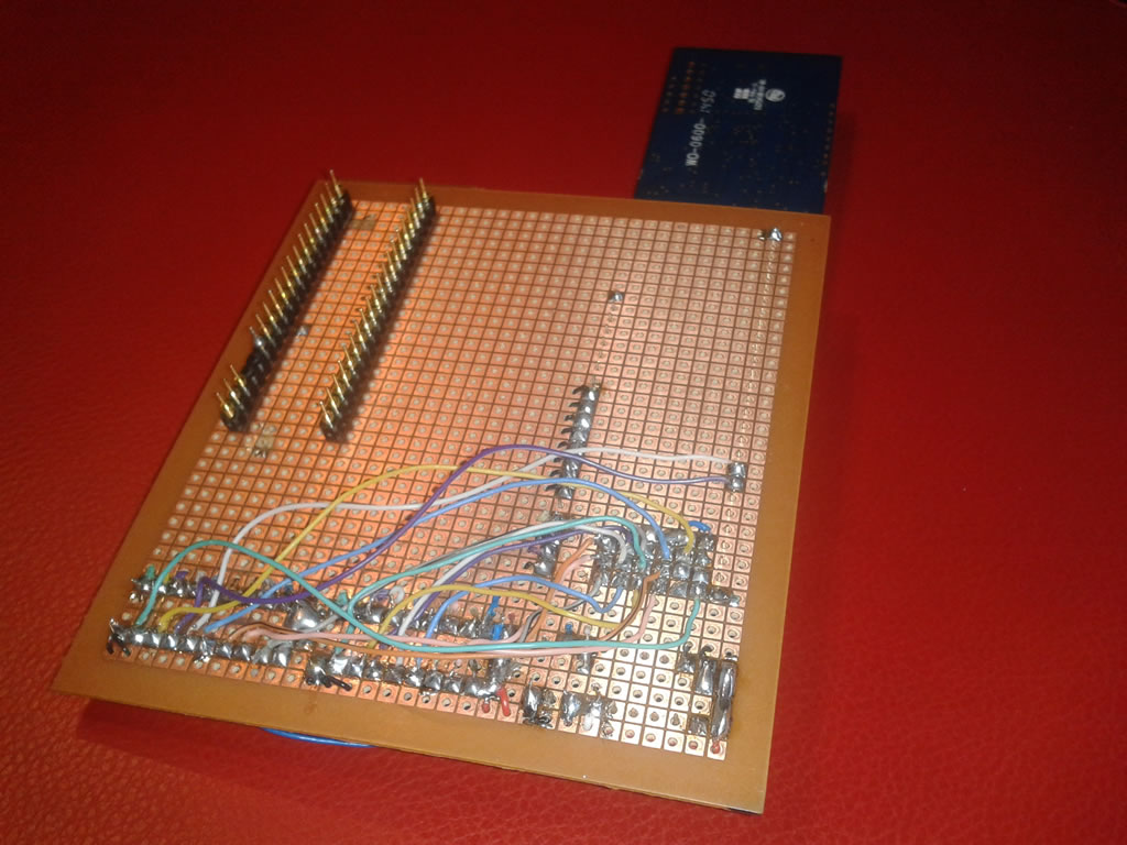
Exploring reconfigurability of the ARM-powered C64 I added a Z80 emulator to the existing 6510 emulator. And for dynamic testing what better than cartridgeless C64 CP/M.
So, heterogeneous multi-software-core C64 is obtained. Of course non-parallel concurrency is obtained, as only one hardware core (ARM) is available.

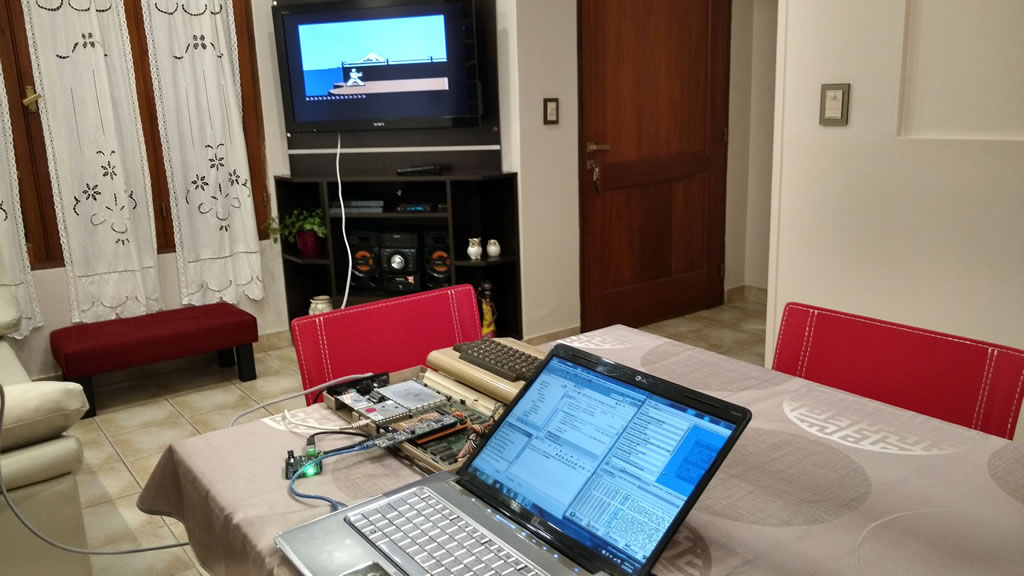
For photos and videos, a very visual (and retro) effect was included, setting screen border color  according to working core (Light Blue: 6510, Red:Z80)


C64 CP/M Background
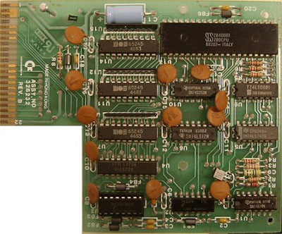
In 80's Commodore developed a CP/M-cartridge that contained a Z80 to benefit C64 of software
available for CP/M. See more about this at Ruud Baltissen's site.

As the original cartridge shares buses between 6510 and Z80 (and also VIC), not allowing simultaneous processors operation, the presented ARM based, non-parallel dual core, is enough for C64 CP/M execution.
Some CP/M BIOS portions, like disk access take advantage of C64 kernal (ROM) and were written for 6510, and CP/M core, running on Z80, calls them continually (as border colors in the video).

6510 core:
In previous post an ARM based C64 was presented, with a C coded 6502 emulator modified for 6510-like operation. It's based on the great Mike Chambers fake6502 emulator.

Z80 emulator
Looking for free portable Z80 C coded emulator I found Marcel de Kogel's Z80emu: "written in pure C, which can be used on just about every 32+ bit system". It was easyly integrated to the existing project IDE: a bare-metal LPC1769 Eclipse workspace.
For ARM compilation "low-endian CPU" option must be declared in Z80.h at "Machine dependent definitions" section.
Z80 use in the C64 cartridge is limited, as  IORQ and interrupts are not used, only memory access must be implemented.

Z80 memory access
User must provide Z80emu with the Z80_RDMEM() and Z80_WRMEM() functions. As buses are shared with 6510 CPU, the same memory access C functions used by 6510 emulator are used by Z80 emulator: externalread() and externalwrite()

/****************************************************************************/
/* Read a byte from given memory location                                   */
/****************************************************************************/
unsigned Z80_RDMEM(dword A){
return(externalread((A&0xffff)+0x1000););
}

/****************************************************************************/
/* Write a byte to given memory location                                    */
/****************************************************************************/
void Z80_WRMEM(dword A,byte V){
externalwrite(((A&0xffff)+0x1000), V&0xff);
}

Note the 0x1000 term added to adresses, recreating the 74LS283 adder included in the CP/M
cartridge for address-space shift. This is so because of the conflict betwheen 6510's I/O port and Z80's reset vector, both located at 0x0000.

Core switching
Without a core scheduler, the C64 CP/M cartridge, implementes a simple scheme. The Z80 is enabled or dissabled writing a byte to an address in the range $DE00/$DEFF with LSB = 0 or 1.
So, core switch is entrusted to software, look how CP/M does it:

6510 assembler code, part of C64 CP/M Bios: http://www.z80.eu/c64/BIOS65.ASM

MODESW = $DE00 1 = Z80 OFF, 0 = Z80 ON

LDA #0 turn Z80 back on
STA MODESW
NOP delay only


Z80 assembler code, part of Z80 bootstrap routine for the C64: http://www.z80.eu/c64/C64BOOT.ASM
OFF EQU 01H
MODESW EQU 0CE00H

MVI A,OFF
STA MODESW ;TURN OFF SELF
NOP

Note MODESW definitios due to address shift.

This functionality was implemented as follows:
A catch in externalwrite() function enables changes the value of a "processor flag" variable (like the Flip Flop in the cartridge )
In main loop, according to "processor flag" variable, one of the following action is performed:

  • Z80 instruction execution
  • 6510 instruction execution and 6510 interrupt  treatment

Recently I found Kernal64, a Scala Commodore 64 emulator supporting CP/M.
Its autor resolved this, long before, in a very simmilar way.

CP/M loading
For previous C64 IEC testing the Uno2IEC was used, but this simple Arduno based drive emulator does not support sector read and write needed by CP/M disk access.
Not having available a disk drive or highly compatible device (SD2IEC, uIEC, etc.) another solution is necessary, described on its own post: Software-core C64 diskless CP/M boot

More photos


C64 powered by ARM running 6502 emulator


A software core for the C64 it's possible. Unlike other implementations based on programmable logic (FPGA) and soft-cores, this is a 32-bit microcontroller running a 6510 emulator. So I call it software-core, no soft-core.
For easy reconfigurability, a portable C programed microprocessor emulator is used resulting in a "High-Level Languaje In-Circuit Emulator".
This is a spacetime emulator use, space because in-circuit, and time because real-time operation (software running synchronized to an extrernal clock).

Watch the videos about a C64 with the 6510 microprocessor replaced with a 32-bit microcontroller: ARM Cortex M3 LPC1769. There are running games and IEC operation (via Uno2IEC).


As you can see, emulation it's not limited to 6510 processor only. Why not implement another CPU emulators for an heterogeneous multi-core C64. In this next post view 6510 and Z80 emulators on ARM for cartridgeless C64 CP/M: Dual Core C64


miker00lz's EhBasic@Arduino
Inspiration:

On Sept 2015 I saw miker00lz’s post at Arduino forum about runnig his 6502 emulator (fake6502) on Arduino (https://forum.arduino.cc/index.php?topic=193216.0).
That was interesting but I thought it would be better if the microcontroller handle external SRAM, CIA or SID.


ARM:
EhBasic@LPC1769 debug console

Thinking that at some point Arduino would limit performance I choose a more powerfull  platform: an NXP LPC1769, ARM Cortex 3. The LPC also has 5V tolerant GPIO pins needed by MOS chips. 
First test was with a 32k x 8 SRAM (HM62256) and fake6502 running EhBasic.


Then GPIO pins were connected to SRAM as 6502 buses, really an incomplete address bus (A0 to A13) beause only 14 contiguous GPIO pins available:  P1.18 to P1.31.


LPCXpresso 1769 Pinout
62256 (32K x 8) SRAM Pinout

And memory read and write functions for fake6502 were written to manage the GPIO pins connected as address, data and control buses.

//MEMORY READ
uint8_t read6502(uint16_t address){
FIO2SET |= (1 << 10); // Pone en H RW* (p2.10) Lectura
FIO2PINH= address << 2; // Escribe la dirección A0 a A13 en P1.18 a P1.31 (bus de direcciones)
FIO2SET |= (1 << 11); // Pone en H CS (p2.11)
value = FIO2PIN0; // Lee bus de datos (P2.0 a P2.7)
FIO2CLR |= (1 << 11); // Pone en L CS (p2.11)
RETURN (value);
}

//MEMORY WRITE
void write6502(uint16_t address, uint8_t value){
FIO2PINH= address << 2; // Escribe la dirección A0 a A13 en P1.18 a P1.31 (bus de direcciones)
FIO2PIN0= value; // Escribe bus de datos (P2.0 a P2.7)
FIO2CLR |= (1 << 10); // Pone en L RW* (p2.10) Escritura
FIO2SET |= (1 << 11); // Pone en H CS (p2.11)
FIO2CLR |= (1 << 11); // Pone en L CS (p2.11)
}


The pins connection was direct and the emulator ran asynchronously, EhBasic code was, like on the Arduino,  contained as a C constant array in the microcontroller flash program memory.


Comparing ROM Dump with ROM Read
C64:
Then I wanted to reproduce 6502 operation reading program from a ROM, that is an external stored program, external to the microcontroller. One first option was to write EhBasic to a 29FXXX DIP Flash but I prefered to use C64 ROMs, so I retired from a C64 a socketed 901225 Characters ROM chip, connected it like the SRAM to the microcontroller and readed it.


And then, one more step, what about connecting the microcontroller to the C64 replacing the original 6510 and test ROM, CIAs and SID with address decoding provided by the original PLA.
It seems trivial but presents several difficulties because in the C64 the 6510 microprocessor shares the buses with the VIC video chip, the system RAM is DRAM refreshed by the VIC chip and we need to emulate 6510’s I/O port.

6510’s I/O port is mapped at $0001 address and, in C64, bits 0,1 and 2 connected to LORAM, HIRAM and CHAREN signals. PLA use this signals for switching between ROM and RAM for $A000-$BFFF, $D000-$DFFF and $E000-$FFFF memory areas.

This operation was implemented with 3 GPIO pins and catchs at write function:

// 6510 I/O Port
if (address==0x1) {
  if ((value & 0x1)==0){
       FIO2CLR = (1 << 11);  // Pone en L LORAM
  }
  else
  {
       FIO2SET = (1 << 11);  // Pone en H LORAM
  }
  if ((value & 0x2)==0){

       FIO2CLR = (1 << 12);  // Pone en L HIRAM
}
   else
   {
        FIO2SET = (1 << 12);  // Pone en H HIRAM
   }
   if ((value & 0x4)==0){
        FIO2CLR = (1 << 13);
   }
   else
   {
        FIO2SET = (1 << 13);  // Pone en H CHAREN
   }
 }

VIC Out
For first tests I removed the VIC chip from the board, but that left me without CPU Clock and without refresh for DRAM, so emulator must use microcontroller RAM. With catchs on memory write function I redirected RAM writes to screen area ($0400-$7fff) to microcontroller debug console and received the C64 startup message. Also pending address lines A14 and A15 were implemented with two aditional GPIOs: P4.28 and P4.29


ROM Read
C64 Boot


VIC:
As VIC provides CLK for CPU up to here the emulator runs asynchronously. In order to place the VIC on the board and share buses the emulator needs third state capability and synchronization to system clock.
In the C64 bus access is driven by VIC with it’s BA signal connected to 6510’s AEC pin. All microprocessor read and write operations take place when AEC=1 and must be enabled by the RDY signal too. When AEC=0 VIC uses the buses and microprocessor pins must go to third state.
For more datails please see: http://www.zimmers.net/cbmpics/cbm/c64/vic-ii.txt


Interface:
That operation was implemented using a custom interface adapter using discrete logic: 3 x 74HC245 Octal 3−State Noninverting Bus Transceivers for address and data bus and a 74HC00 for R/W. Two remaining 74HC00 gates were used to accommodate required delay between in and out 6510 clock signals.


Also read and write functions were rewritten in order to take into account AEC and RDY states.

As 6510 only can access buses when AEC=HIGH all read and write operations are synchronized to that signal and not to Clk (Fi2).


//MEMORY READ (SHARED BUS)
uint8_t externalread(uint16_t address) {
uint8_t  value;
    while ((FIO2PIN1&1)==0) {}; // Espera mientras AEC=0 -> Fi0(P2.8)=0
while ((FIO2PIN1&1)==1) {}; // Espera mientras AEC=1 -> Fi0(P2.8)=1
FIO1PINH =(address << 2); // Escribe la dirección A0 a A13 en P1.18 a P1.31 (bus de direcciones)
FIO4PINH= (address >> 2); // A14 y A15 en P4.28 y P4.29
while ((FIO0PIN3&16)==0){}; // Si RDY=0 (P0.28) espero aquí
    while ((FIO2PIN1&1)==0) {}; // Espera mientras AEC=0 -> Fi0(P2.8)=0
while ((FIO2PIN1&1)==1) {}; // Espera mientras AEC=1 -> Fi0(P2.8)=1
value = FIO2PIN0; // Lee bus de datos (P2.0 a P2.7)
// DEBUGOUT ("<> %x %x\n",address,value);
return(value);
}

//MEMORY WRITE (SHARED BUS)
void externalwrite(uint16_t address, uint8_t value) {
while ((FIO2PIN1&1)==0) {}; // Espera mientras AEC=0 -> Fi0(P2.8)=0
FIO2PIN0 = value;     // Escribe bus de datos (P2.0 a P2.7)
while ((FIO2PIN1&1)==1) {}; // Espera mientras AEC=1 -> Fi0(P2.8)=1
////////////////////FLANCO DESCENDENTE////////////////////
FIO1PINH =(address << 2); // Escribe la dirección A0 a A13 en P1.18 a P1.31 (bus de direcciones)
FIO4PINH= (address >> 2); // A14 y A15 en P4.28 y P4.29
FIO2SET = (1 << 10); // Pone en H W (P2.10) Escritura
FIO2DIR0 = 0xff;    // Bus de datos como Salida
   while ((FIO2PIN1&1)==0) {}; // Espera mientras AEC=0 -> Fi0(P2.8)=0
while ((FIO2PIN1&1)==1) {}; // Espera mientras AEC=1 -> Fi0(P2.8)=1
////////////////////FLANCO DESCENDENTE////////////////////
FIO2PIN0 = value;     // Escribe bus de datos (P2.0 a P2.7)
FIO2DIR0 = 0x00; // Bus de datos como Entrada
FIO2CLR = (1 << 10); // Pone en L W (P2.10) Lectura
}


Timmings:
VIC chip was connected to the board and several time adjustments were made to read/write routines.
Incorrect timmings produced DRAM corruption during VIC refresh and access.


Ram Corruption
Error: 38911./909 Bytes Free


Finally I got the system running, a C64 with a software-emulated microprocessor!


Testing;
 The shared bus access works fine even with the lower performance obtained, about 60%, respect to the original 1MHz 6510.


Games and default IEC bus was tested using Uno2IEC, a 1541 IEC interface emulator using Arduino.
Of course better performance can be achieved using an assembly emulator, like a6502 (https://github.com/BigEd/a6502), but the idea is a "High-Level Languaje In-Circuit Emulator".


More photos